Die nachfolgende Arbeit ist im Fachausschuss „Chemische Metallabscheidung“ der Deutschen Gesellschaft für Galvano- und Oberflächentechnik e.V. DGO entstanden und vermittelt einen Teil der dort erarbeiteten Ergebnisse
1) Technische Universität Ilmenau, Fachgebiet Elektrochemie und Galvanotechnik
2) Pontificia Universidad Católica del Perú, Instituto de Corrosión y Protección
1 Introduction
Nowadays industrial sectors such as automotive, aerospace, electronics and textile increasingly
require the use of materials with suitable properties for specific applications. One possibility to improve materials performance is to protect them by coatings.
Ni-P alloys obtained by electroless plating have contributed to a significant advance in the development of protective coatings because a Ni-P coating improves basis material properties such as corrosion resistance, hardness, wear resistance and surface uniformity [1, 2]. The addition of dispersed, hard micro/nano particles into the Ni-P matrix has led to the development of composite coatings. Ni-P composite coatings exhibit an improved hardness and wear resistance. However, it is difficult to predict accurately their corrosion resistance because different parameters can influence the behaviour of these coatings. In fact, the role of dispersed particles for the corrosion properties is still controversially discussed [3, 4, 5].
This research aims to synthetize, to characterize and to evaluate the corrosion resistance in NaCl 3.5 % of as-plated Ni-P and Ni-P-SiC coatings with high phosphorus content. By using different electrochemical techniques a better understanding of the behaviour of Ni-P and Ni-P-SiC can be achieved.
2 Experimental part
2.1 Synthesis of electroless Ni-P and Ni-P-SiC coatings
Electroless Ni-P and Ni-P-SiC deposits were obtained by electroless deposition using both lab made and commercial nickel/hypophosphite based baths. The chemical composition of the lab made plating bath consisted of:
- 30 g/L NiSO4·7H2O,
- 20 g/L NaH2PO2·H2O,
- 25 g/L lactic acid,
- 5 g/L propionic acid,
- 1 mg/L Pb2+ (as Pb(NO3)2)
In the case of the plating baths used for the composite coatings, 25 g/L of SiC micro-sized particles (2 µm to 5 µm, ESK Ceramics GmbH & Co. KG, Kempten) were added to the original lab made and commercial baths. The pH value of all plating baths was adjusted to 4.8 with 5M NaOH solution. All reagents were p.a. grade.
Low carbon steel panels (2.5 x 4.5 x 0.05 cm3) were used as substrates. The pre-treatment of the substrates consisted of an electrolytic degreasing for 3 minutes at a current density of 6.5 A/dm2 (cathodic mode) followed by a substrate pickling with HCl (1:1 v/v) for 3 minutes. Both procedures were done at room temperature.
In all the cases the plating was carried out by immersing the substrate into the electrolytic bath at 87 ± 1 °C immediately after the pre-treatment. The bath loading was 0.15 dm2/L and the deposition time was 2 hours. In the case of Ni-P-SiC deposits, the electroless baths containing dispersed SiC particles were mechanically stirred at approx. 500 rpm with a two-bladed glass stirring element. The sample was vertically positioned and parallel oriented to the flow direction of the bath. After the deposition process the samples were rinsed with distilled water, dried and stored in a desiccator.
2.2 Characterization of deposits
The surface morphology of deposits was studied by scanning electron microscopy (SEM) using a Philips XL 30 scanning electron microscope. The samples were examined in top and cross-sectional views. The chemical composition of deposits was determined by GD-OES with a GDA 750 Sprectruma equipped with a DC source (1000 V, 13 mA). The diameter of the exposed sample area was 2.5 mm. The microstructure of Ni-P and Ni-P-SiC deposits was studied by X-ray diffraction (XRD). An X-ray diffractometer (Bruker AXS D 5000 operating with Cu-Kα radiation) with Goebel mirror was used. The studied sample area was approx. 1 cm2. The method of study was grazing incidence diffraction [6].
The coatings thickness were determined by magnetic induction method and then verified by SEM in the surface cross-section of the samples. A Deltascope MP30 (Fischer) thickness tester was used according with ASTM B 499-96 standard [7].
2.3 Corrosion resistance of deposits
All the electrochemical tests were performed using an Autolab PGSTAT 302N potentiostat/galvanostat equipped with a FRA2 impedance module and controlled with the software NOVA version 1.4. The electrochemical tests used a conventional three-electrode electrochemical cell setup: the sample (Ni-P or Ni-P-SiC deposit) as the working electrode (WE), a silver/silver chloride electrode (Ag/AgCl 3M KCl) as the reference electrode (RE) and a platinum wire as the counter electrode (AE). The electrochemical cell consisted of a glass cylinder with a PTFE bottom plate with a hole in the centre. The exposed sample area was 0.20 cm2. All tests were carried out at room temperature.
The electrolytic solution was prepared by dissolving NaCl (p.a., Merck) in distilled water to give a concentration of 3.5 wt.%. In order to carry out tests with a constant concentration of oxygen in the salt solution, the electrolyte was air-saturated by bubbling air for 30 minutes. About 40 mL of electrolyte was used for each test. The OCP (open circuit potential) measurement was performed monitoring the potential of the sample (WE) in the 3.5 wt.% NaCl solution versus the reference electrode (RE) for 1 hour.
Potentiodynamic anodic polarization studies were carried out by scanning the potential +1.0 V from the OCP value. Tafel plots were obtained by scanning the potential from -0.25 V to +0.25 V from OCP. LPR plots were obtained by scanning the potential from -0.02 V to +0.02 V from OCP. All tests were carried out with a scan rate of 0.16 mV/s. EIS measurements were carried out by applying a small amplitude voltage of 10 mV (single sine wave type) to the previously determined OCP value. The frequency ranged from 10 kHz to 1 mHz. The number of frequencies was 50.
All potentials from experimental data were converted to the saturated calomel electrode (SCE) scale to facilitate the discussion.
3 Results and discussion
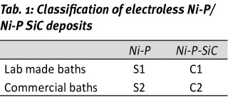
The Ni-P and Ni-P-SiC coatings obtained from electroless plating process were classified according to the baths employed for their synthesis. The used nomenclature of the samples is summarized in Table 1.
3.1 Morphology
The scanning electron micrographs of the deposits in top and cross sectional view are shown in Figure 1 and Figure 2. For both Ni-P deposits S1 (Fig. 1a) and S2 (Fig. 1c), a regular, continuous and relatively smooth morphology is observed. Deposit S2 shows the presence of micro-pores uniformly distributed over the surface (Fig. 1c). Cross sectional view (Fig. 2c) also confirmed the presence of pores.

Fig. 1: SEM micrographs in top view of Ni-P and Ni-P-SiC deposits: a) S1 (1000X), b) C1 (4000X), c) S2 (1000X) and d) C2 (4000X)

Fig. 2: SEM micrographs in cross sectional view of Ni-P and Ni-P-SiC deposits: a) S1 (2000X), b) C1 (1000X), c) S2 (2364X) and d) C2 (4000X)
In the case of the Ni-P-SiC composite deposits C1 (Fig. 1b and 2b) and C2 (Fig. 1d and 2d), a coarse morphology with uniform distribution of SiC particles can be observed. There are neither agglomerated nor depleted zones of particles. The incorporation of dispersed SiC micro-particles seems to prevent the growth of pores as well.
3.2 Chemical composition
Figure 3 shows a comparison of the average results of chemical analysis carried out by GD-OES. It can be seen that composite deposits have similar content of incorporated SiC microparticles: deposit C1 with 9.4 wt% SiC and deposit C2 with 11.4 wt% SiC. All deposits are considered to be high phosphorous coatings [1].

Fig. 3: Average results from GD-OES chemical analysis of deposits S1, S2, C1 and C2
Since microstructure, corrosion behavior and other properties are depending on the phosphorous content in Ni-P deposits [1], a detailed description of the phosphorous content across the thickness of the deposits can be seen in Figure 4. In this case, for the evaluation of the phosphorous content of the Ni-P alloy (or Ni-P alloy matrix in the case of C1 and C2), only Ni and P were considered (without regarding the particles in the case of composite deposits).
Comparing the phosphorous content as depth-profile analysis of all deposits (Fig. 4), it can be seen that the phosphorous content is not uniform across the thickness. At the surface, the phosphorous contents are higher than in the bulk. This is due to the slight decrease of the pH values of the baths during the plating process. Deposits resulting from commercial baths (S2 and C2) have higher phosphorous content because these baths also contained a higher quantity of hypophosphite (0.27 M) in comparison to lab made baths (0.18 M). On the other hand, by comparing the phosphorous content of the Ni-P deposits (S1 and S2) with their analogous composites (C1 and C2), it can be seen that phosphorous contents in composite deposits are lower than those of the pristine deposits. Thus, the presence of SiC particles seems to affect the phosphorous content of the Ni-P matrix of the composite deposits. Other works about electroless Ni with SiC and TiO2 particles also reported this observation [8, 9].

Fig. 4: Phosphorous content in Ni-P matrix of deposits as depth-profile analysis (* - only Ni and P (100%) were considered)
The SiC content of the composite deposits C1 and C2 across their thickness can be considered constant. This means that SiC particles are well distributed in the metal matrix. Figure 5a shows the GD-OES depth-profile analysis for deposit C1 and Figure 5b shows a SEM micrograph of deposit C1 in cross sectional view showing the uniform distribution of particles as well.

Fig. 5: SiC particle content distribution on deposit C1: a) Detailed depth profile analysis by GD-OES, b) SEM micrograph in cross sectional view (1000X)
3.3 Microstructure
The X-ray diffraction patterns of the as-deposited Ni-P and Ni-P-SiC coatings are shown in Figure 6. All XRD patterns have a common broad diffraction peak at the wide angular range of approx. 40° to 50° (2θ), those broad peaks were located around the 44.5° (2θ) position corresponding to the (111) diffraction peak of nickel. That indicates the amorphous character of the Ni-P matrix of the four deposits [1, 2, 10].
With a higher phosphorous content in the coating, the disorder of the nickel structure will also be higher and the structure becomes amorphous [11]. GD-OES analysis had shown that all deposits have high phosphorous contents, especially near the surfaces. Hence, these high phosphorous contents have influenced on the distortion of the lattice of nickel and resulted in amorphous structures of the deposits.
Additionally, X-ray diffraction patterns of composite deposits C1 and C2 show some well-defined peaks corresponding to the crystal lattices of the 6H-SiC hexagonal polytype micro-particles.
3.4 Thickness of the deposits
Table 2 compares the thicknesses obtained by the magnetic induction method and SEM, respectively. The values obtained via the magnetic induction method represent average values; on the other hand, the values taken from SEM represent the thickness in a specific zone. The data imply that all the deposits have uniform thicknesses.
Deposits S1 and C1 (from lab made baths) were the ones with higher thickness values. The presence of particles in the plating baths had an influence on the deposition rate of the deposits. No clear relationship was found since by comparing deposits S1 and C1, the deposition rate of deposit C1 was higher and, on the other hand, by comparing deposits S2 and C2, the deposition rate of deposit C2 was lower.
3.5 Corrosion resistance by electrochemical techniques
3.5.1 Potentiodynamic anodic polarization
The potentiodynamic anodic polarization plots of deposits in 3.5 wt.% NaCl are depicted in Figure 7. The current density is plotted in logarithmic scale.
At anodic potentials near the OCP the current densities of all the deposits were very low, this suggests the existence of a protective layer. According to other investigations [5, 12-14], for Ni-P deposits with high phosphorous content, a preferential dissolution of nickel occurs near the OCP leading to the enrichment of phosphorous on the surface layer. Balaraju et al. [5] reported that the barrier-action of the phosphorous enriched surface layer is related to the reaction of such layer with water to form a layer of adsorbed hypophosphite anions. This layer in turn would block the supply of water to the surface avoiding its dissolution.
At potentials above +0.3 V vs. SCE the current density increased quickly, which suggests that all deposits began to dissolve faster since, at high polarization conditions, the protective layer dissolves and nickel is oxidized to Ni2+ and Ni3+. Deposit C1 is the one, which experienced the highest dissolution current; this could be attributed to the lower P content in the bulk Ni-P matrix in comparison with the other samples.
After the anodic polarization test, pits were observed in deposit S2. According to the morphology of deposits, the presence of micropores was found in deposit S2. Thus, the occurrence of pits on deposit S2 (due to the reaction of the medium with the substrate) was expected. No pits were found on deposits S1, C1, and C2.
Special attention deserves the fact that the composite deposit C2 did not show presence of pits after anodic polarization in comparison to its analogous Ni-P deposit (S2). It can be concluded that the presence of dispersed SiC micro-particles prevented the growth of micro-pores during the deposition of C2.
3.5.2 Cathodic and anodic polarization
The Tafel plots are depicted in Figure 8. All deposits showed a Tafel behaviour since the corrosion process is controlled by charge transfer over a wide potential range [15]. By extrapolating the linear portions of the polarization plots it was possible to calculate the electrochemical parameters (Tab. 3). Studies of EIS (see below) confirmed that charge transfer is the mechanistic pathway controlling the corrosion process of all deposits.
The composite deposits (C1 and C2) showed a lower corrosion current density (icorr) than the pristine deposits; among them, deposit C1 was the one with the lowest corrosion current density. The Stern-Geary constant (B) was calculated from the Tafel slopes values βa and βb for each system [15].
3.5.3 Linear polarization curves
The electrochemical parameters obtained from LPR plots are described in Table 4. The composite Ni-P-SiC deposits showed the higher polarization resistance values (Rp).
3.6 Electrochemical impedance spectroscopy
The Nyquist plots (Fig. 9) of all deposits have, as a common feature, one big capacitive loop. That represents one time-constant on the impedance spectra and, in consequence, one reaction on the electrode/electrolyte interface responsible for the corrosion behaviour of each sample. Thus, the charge transfer resistance (Rct) is considered to be the electrochemical parameter that indicates the corrosion resistance of deposits. Thus, Rct can be identified as the polarization resistance (Rp).
A Randles circuit (Fig. 10) was used to fit the data; this circuit simulates the electrochemical behavior of the Ni-P/Ni-P-SiC surface-solution interface. It contains elements corresponding to the solution resistance (Rs) placed in series with a circuit element composed of a charge transference resistance (Rct) in parallel with a double-layer capacitance (Cdl). To model the double-layer capacitance (Cdl), a constant phase element (CPE) was used instead of the Cdl. The use of a CPE is recommended in order to compensate the heterogeneity of the system [16]. In this case, an example of heterogeneity is the higher roughness of deposits C1 and C2 as a consequence of the presence of dispersed SiC micro-particles. The CPE is defined by two parameters, Y0 (admittance) and α (an empirical exponent related to the surface roughness). If α is equal to 1, the CPE is identical to a capacitor. Values of the double layer capacitance (Cdl) were calculated from the CPE parameters [14]. ωmax is the frequency of the maximum of Z’’ (imaginary component of impedance).
Table 5 summarizes the electrochemical parameters obtained from EIS experiments. Rct values of
Ni-P-SiC composite deposits are a little bit higher than the ones obtained for Ni-P deposits.
3.7 Comparison of results
The corrosion current density (icorr) for each deposit was calculated using the Rct (or Rp) values obtained from LPR and EIS experiments by using the Stern-Geary simplified kinetic expression. Additionally, the corrosion current density (icorr) of deposits was also obtained directly from the Tafel plots [15]. Figure 11 depicts the corrosion current density values obtained from LPR, EIS and Tafel plots techniques.
According to Figure 11, the better corrosion behavior of the Ni-P-SiC composite deposits (C1 and C2) in comparison with Ni-P deposits (S1 and S2) is evident. The three electrochemical techniques used in this investigation confirm this behavior.
The characterization of Ni-P deposits (S1 and S2) and Ni-P matrices from composite deposits (C1 and C2) have demonstrated that their microstructure and chemical composition are similar. Then the behavior of these deposits in a corrosive environment is expected to be similar, the corrosion current densities obtained for this deposits confirm this fact. In the case of composite deposits, considering that SiC particles are chemically inert in a salt solution medium, the origin of the lower corrosion current densities is attributed to the lower available surface metallic area at the metal/solution interface.
4 Conclusions
By using lab made and commercial nickel/hypophosphite based baths, high phosphorous Ni-P /Ni-P-SiC deposits were obtained through an electroless plating process. In the case of composite deposits, the amount of incorporated SiC particles was about 10 wt.%.
All deposits showed an amorphous micro-structure and high phosphorous content. Depth profile analysis of deposits by GD-OES demonstrated that the phosphorous content of deposits is not uniform across their thickness. At the surface, the phosphorus contents were higher than in the bulk. This fact implies a phosphorous enrichment at the surface of the deposits.
Comparative studies of morphology (presence of pores) and examination of occurrence of pits (after anodic polarization tests) between deposits synthesized with commercial baths (S2 and C2) indicate that the presence of dispersed SiC micro-particles prevented the growth of micro-pores during the synthesis of C2.
The electrochemical methods (LPR, EIS, Tafel plots) used to study the corrosion resistance of Ni-P and Ni-P-SiC composite coatings in 3.5 wt.% NaCl solution showed that Ni-P-SiC composite coatings experience lower corrosion currents compared to the Ni-P coatings. This fact can be ascribed to the decrease in the effective area available for corrosion. Concerning to the mechanism by which the Ni-P and Ni-P-SiC become corroded, EIS experiments demonstrated that the corrosion process involved a charge transfer mechanism. Tafel plots also corroborated the charge transfer mechanism since all deposits showed a Tafel behavior in 3.5 wt.% NaCl solution.
Acknowledgements
The authors would like to express their appreciation to the financial support of the ISAP-DAAD exchange program and to the LUCET 90 Project L-004 granted to the Instituto de Corrosión y Protección of the Pontificia Universidad Católica del Perú. The authors wish also to acknowledge Dipl.-Ing. M. Wilke, Dr.-Ing. K. Pfeifer and Dipl.-Ing. R. Grieseler for their valuable support in GD-OES, SEM and XRD measurements, respectively.
References
[1] Mallory, G. O.: Electroless Plating: Fundamentals and Applications (Reprint Ed.), USA: Noyes Publications/ William Andrew Publishing (1990)
[2] Kanani, N: Chemische Vernicklung: Nickel-Phosphor-Schichten: Herstellung – Eigenschaften –Anwendungen, Germany, Leuze (2007)
[3] Davis, R. J.: Nickel: Cobalt and their Alloys (1st Ed.).USA: ASM International (2000)
[4] Balaraju, J. N., Sankara, T. S. N., Seshadri, S. K.: Electroless Ni-P composite coatings, Journal of Applied Electrochemistry, 33, 807-816 (2003)
[5] Balaraju, J. N., Sankara Narayanan, T. S. N., Seshadri, S. K.: Evaluation of the corrosion resistance of electroless Ni-P and Ni-P composite coatings by electrochemical impedance spectroscopy, Journal of Solid State Electrochemistry, 5, 334-338 (2001)
[6] Spieß, L., Teichert, G., Schwarzer, R., Behnken, H., Genzel, C.: Moderne Röntgenbeugung (2d Ed.) Germany: Vieweg+Teubner (2009)
[7] ASTM B 499: Standard Test Method for Measurement of Coating Thicknesses by the Magnetic Method: Nonmagnetic Coatings on Magnetic Basis Metals (2002)
[8] Jiaqiang, G., Lei,L., Yating W., Bin, S., Wenbin, H.: Electroless Ni–P–SiC composite coatings with superfine particles.Surf. Coat. Technol. 200 (20-21) 5836 (2006)
[9] Novakovic, J., Vassiliou, P., Samara, Kl., Argyropoulos, Th.: Electroless NiP-TiO2 composite coatings: Their production and properties.Surf. Coat. Technol. 201(3-4) (2006) 895
[10] Keong, K. G., Sha, W., Malinov S.: Crystallisation kinetics and phase transformation behaviour of electroless nickel-phosphorus deposits with high phosphorus content. Journal of Alloys and Compounds, 334, 192-199 (2002)
[11] Balaraju, J. N., Rajam, K. S.: Electroless Deposition and Characterization of High Phosphorus Ni-P-Si3N4 Composite Coatings. Int. J. Electrochem. Sci., 2, 747-761 (2007)
[12] Bigdeli, F., Allahkaram, S. R.: The Corrosion Behaviour of Electroless Ni-P-SiC Nano-Composite Coating. International Journal of Modern Physics B, 22, 3031-3036 (2008)
[13] Elsener, B., Crobu, M., Scorciapino, M. A., Rossi, A.: Electroless deposited Ni-P alloys: corrosion resistance mechanism. Journal of Applied Electrochemistry, 38, 1053-1060 (2008)
[14] Królikowski, A., Karbownicka, B., Jaklewicz, O.: Anodic dissolution of amorphous Ni-P alloys. Electrochimica Acta, 51, 6120-6127 (2006).
[15] Thompson, N. G., Payer, J. H.: DC Electrochemical Test Methods (1st Ed.). USA: NACE International (1998)
[16] Frankel, G. S.: Electrochemical Techniques in Corrosion: Status, Limitations, and Needs. Journal of ASTM International, 5, No. 2 (2008)